5年ぶりにSTM32マイコンのプログラミングです。
この間、mbedオンラインコンパイラーが廃絶してしまったので、今回は、STM社のサイトにいって
開発環境をどれにしようかと迷いましたが、一番簡単なArduinoIDEでSTM32マイコンを使える
STM32duinoというTOOLをつかうことにしました。
●STM32duinoのインストール解説ページ
こちらのページの解説が丁寧です。24年夏に更新されていて最新です。作者様に感謝です。
https://note.com/kuribata/n/n16dbbdb8978f
手順ゼロ:ArduinoIDE最新版がインストールされていること。今回使ったのは、ArudinoIDE ver2.3.4です。
手順1:ArduinoIDEのpreferencesのCPU製造元のURLを入力するボックスに 下記URL追加
https://github.com/stm32duino/BoardManagerFiles/raw/main/package_stmicroelectronics_index.json
手順2:ボードマネージャーにSTM32を検索して登録させる。
手順3:STM32CUBE Programmerをダウンロードしてインストール
ST社のページからダウンロードします。会員登録する必要があります。
https://www.st.com/ja/development-tools/stm32cubeprog.html#get-software
ZIPを解凍して、SetupSTM32CubeProgrammer_win64.exe
を実行すると自動でArduinoIDEにインストールされます。
これで、環境は出来上がりです。
●実行までの操作
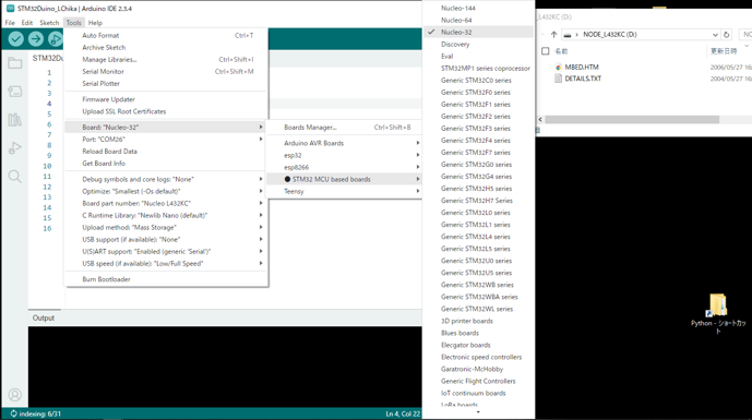
①ボードマネージャを開いてnucleo32を選択
下のほうに borard part number があるのでクリックしてドロップダウンメニューからボード名を選択
ここではL432kcです。
ボードをUSB接続すると右のようにフラッシュの中身が表示されますが、コンパイルには無関係です。
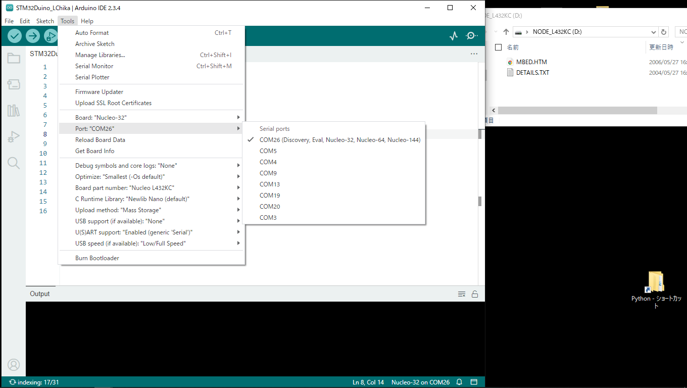
②USB接続して、COMポート選択
ここではCOM26 Discover Eval Nucleo32
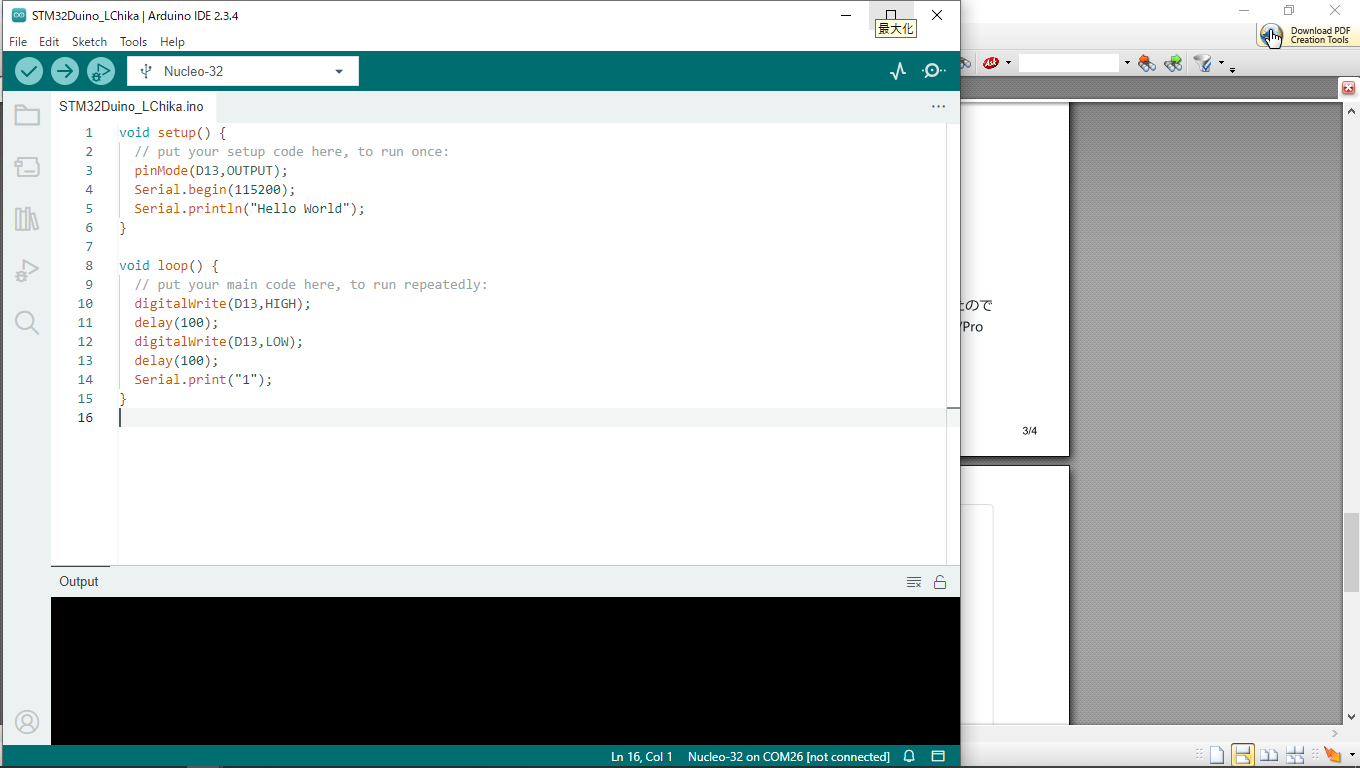
③Lチカプログラム 実行OK
少しコンパイル遅いです、M5シリーズくらい遅いです。Teensyの高速コンパイルに慣れていると遅く感じます。Lチカと1という文字をシリアルプリントしてます。
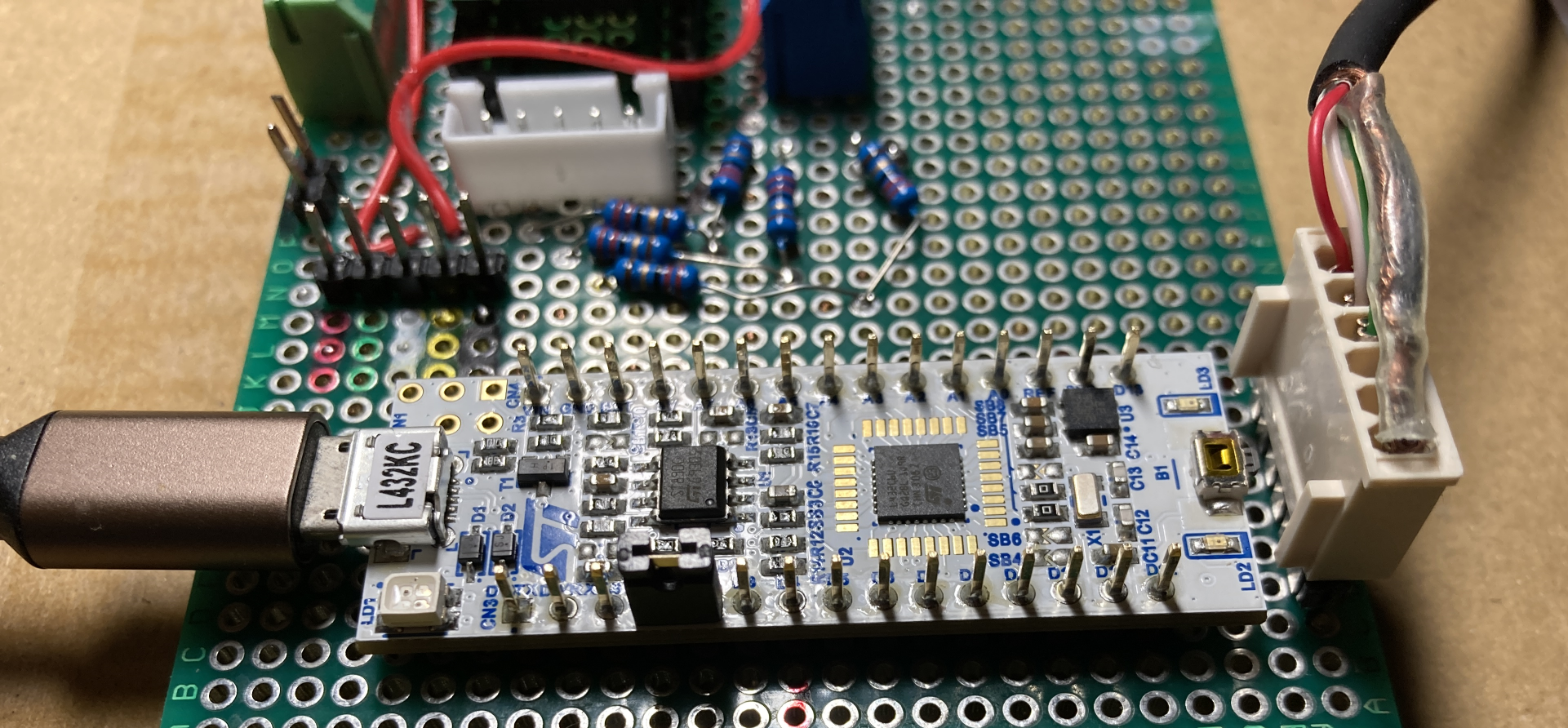
●I2C結線のチェック
最初に、I2Cが動くかをテストしました。
これは、ArduinoIDEのFile>example>wire>i2c scannerというサンプルプログラムに使っているSDA,SCLピン番号を追記して、I2C番号が検出されれば、接続OKとなります。 追記した2行だけで、赤文字です。
|
// ————————————–
// i2c_scanner
//
// Version 1
// This program (or code that looks like it)
// can be found in many places.
// For example on the Arduino.cc forum.
// The original author is not know.
// Version 2, Jun 2012, Using Arduino 1.0.1
// Adapted to be as simple as possible by Arduino.cc user Krodal
// Version 3, Feb 26 2013
// V3 by louarnold
// Version 4, March 3, 2013, Using Arduino 1.0.3
// by Arduino.cc user Krodal.
// Changes by louarnold removed.
// Scanning addresses changed from 0…127 to 1…119,
// according to the i2c scanner by Nick Gammon
// http://www.gammon.com.au/forum/?id=10896
// Version 5, March 28, 2013
// As version 4, but address scans now to 127.
// A sensor seems to use address 120.
//
// This sketch tests the standard 7-bit addresses
// Devices with higher bit address might not be seen properly.
//
/* Example pinmap for Bluepill I2Cs (by Testato)
I2C-1 standard pins: PB7(sda) PB6(scl)
Use it by “Wire” without pin declaration
Wire.begin();
I2C-1 alternative pins: PB9(sda) PB8(scl)
Remap the first I2C before call begin()
Wire.setSDA(PB9);
Wire.setSCL(PB8);
Wire.begin();
I2C-2: PB11(sda) PB10(scl)
Remap the second I2C before call begin()
Wire.setSDA(PB11);
Wire.setSCL(PB10);
Wire.begin();
If you want to use the two I2Cs simultaneously, create a new instance for the second I2C
TwoWire Wire2(PB11,PB10);
Wire2.begin();
*/
#include <Wire.h>
h
void setup() {
Serial.begin(115200);
Wire.setSDA(D4);//Nucleo L432KCのI2C1のSDAピン
Wire.setSCL(D5);//Nucleo L432KCのI2C1のSCLピン
Wire.begin();
Serial.println(“\nI2C Scanner”);
}
void loop() {
byte error, address;
int nDevices;
Serial.println(“Scanning…”);
nDevices = 0;
for(address = 1; address < 127; address++) {
// The i2c_scanner uses the return value of
// the Write.endTransmisstion to see if
// a device did acknowledge to the address.
Wire.beginTransmission(address);
error = Wire.endTransmission();
if (error == 0) {
Serial.print(“I2C device found at address 0x”);
if (address < 16)
Serial.print(“0”);
Serial.println(address, HEX);
nDevices++;
}
else if (error == 4) {
Serial.print(“Unknown error at address 0x”);
if (address < 16)
Serial.print(“0”);
Serial.println(address, HEX);
}
}
if (nDevices == 0)
Serial.println(“No I2C devices found”);
else
Serial.println(“done”);
delay(5000); // wait 5 seconds for next scan
}
|
このi2c scannerを走らせると接続デバイスのI2cアドレスがでてくれば接続OKです。
出てこなければ結線が間違っているかプルアップ抵抗が入ってないとか、ケーブルのシールドが悪くてノイズが入っているとかハードの問題だと判ります。
o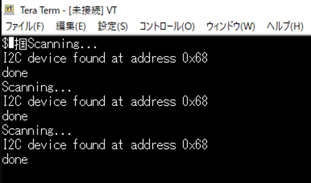
●MPU6500のプログラム
Teensyだと、Arduinoプログラムのライブラリーのほとんどに対応しているのですが、STM32duinoでは、
MPU6500のライブラリーでは動作しませんでした。
そこで、ライブラリー無しの、手動接続のArduinoサンプルプログラムを探して、I2Cポート名だけ変更させて
何とか動作できました。
こちらのブログ様から、サンプルプログラムをいただいて感謝です。
とある科学の備忘録 様
https://shizenkarasuzon.hatenablog.com/entry/2019/02/16/162647#3%E3%82%B5%E3%83%B3%E3%83%97%E3%83%AB%E3%83%97%E3%83%AD%E3%82%B0%E3%83%A9%E3%83%A0
追加部分だけ赤文字
|
#include <Wire.h>
// MPU-6050のアドレス、レジスタ設定値
#define MPU6050_WHO_AM_I 0x75 // Read Only
#define MPU6050_PWR_MGMT_1 0x6B // Read and Write
#define MPU_ADDRESS 0x68
// デバイス初期化時に実行される
void setup() {
Wire.setSDA(D4);//NucleoL432KCのI2c1のSDAピン名
Wire.setSCL(D5);//NucleoL432KCのI2c1のSCLピン名
Wire.begin();
// PCとの通信を開始
Serial.begin(115200); //115200bps
// 初回の読み出し
Wire.beginTransmission(MPU_ADDRESS);
Wire.write(MPU6050_WHO_AM_I); //MPU6050_PWR_MGMT_1
Wire.write(0x00);
Wire.endTransmission();
// 動作モードの読み出し
Wire.beginTransmission(MPU_ADDRESS);
Wire.write(MPU6050_PWR_MGMT_1); //MPU6050_PWR_MGMT_1レジスタの設定
Wire.write(0x00);
Wire.endTransmission();
}
void loop() {
Wire.beginTransmission(0x68);
Wire.write(0x3B);
Wire.endTransmission(false);
Wire.requestFrom(0x68, 14, true);
while (Wire.available() < 14);
int16_t axRaw, ayRaw, azRaw, gxRaw, gyRaw, gzRaw, Temperature;
axRaw = Wire.read() << 8 | Wire.read();
ayRaw = Wire.read() << 8 | Wire.read();
azRaw = Wire.read() << 8 | Wire.read();
Temperature = Wire.read() << 8 | Wire.read();
gxRaw = Wire.read() << 8 | Wire.read();
gyRaw = Wire.read() << 8 | Wire.read();
gzRaw = Wire.read() << 8 | Wire.read();
// 加速度値を分解能で割って加速度(G)に変換する
float acc_x = axRaw / 16384.0; //FS_SEL_0 16,384 LSB / g
float acc_y = ayRaw / 16384.0;
float acc_z = azRaw / 16384.0;
// 角速度値を分解能で割って角速度(degrees per sec)に変換する
float gyro_x = gxRaw / 131.0;//FS_SEL_0 131 LSB / (°/s)
float gyro_y = gyRaw / 131.0;
float gyro_z = gzRaw / 131.0;
Serial.print(acc_x); Serial.print(“,”);
Serial.print(acc_y); Serial.print(“,”);
Serial.print(acc_z); Serial.print(“,”);
Serial.print(gyro_x); Serial.print(“,”);
Serial.print(gyro_y); Serial.print(“,”);
Serial.print(gyro_z); Serial.println(“”);
}
|
これで、一発動作OKでした。STM32は、結構1発で動いてくれることが多いので好きです。
●MPU6500 2個接続のプログラム
MPU6500を2個を接続する場合、アドレスを0x68と0x69となります。
AD0ピンを3.3vにすると0x69になります。
D4,D5に2個のSDA,SCLを接続します。プルアップ抵抗は一対で大丈夫です。
プログラム上の注意は、受信が終わったら、
で、i2cを閉じて次のアドレスは最初からスタートさせます。
関数をつくって、アドレスを引数にしました。
サンプルプログラムのi2c部分のタイミングがうるさくて、printを追加すると動作しなくなるという現象が
でたので、一切いじらないで、関数をつくって、アドレスだけ交換するようにしました。
プログラムは、gistにおいてあります。
https://gist.github.com/dj1711572002/037b96e094a02a7072e85b3bb789def0
●以後
2個のMPU6500を付けます。更に6芯のシールドケーブルにいれて、UARTと同居させて1m引き回すので
I2Cがこけるリスクがあるので、それを実験して確認します。